

Views: 0 Author: Site Editor Publish Time: 2026-09-20 Origin: Site


maintenance of bridge
When the drive axle is in use, whether the parts can play a normal function, and whether it can use and maintenance reasonably is very important. In order to cooperate with users to use reasonably, pay attention to maintenance and carry out simple repair by oneself, make the product often maintain a good technical state, extend its service life, better play the function of the product to provide some basic knowledge, for reference
• | Coupling of rim to bridge |
The rim nut is M22×1.5, and its tightening torque is 700 ~ 800 n.m. When tightening a set of rim nuts, it must be done symmetrically and evenly.In normal use should often check whether the nut is loose, timely tightening it. When using spherical rim nut, check whether the spherical nut and rim socket match, should ensure that the spherical match, so that the connection is strong.
• | lubrication
|
• | Refueling position and quantity |
The oil level holes on both sides of the left and right balance box assembly are oil level observation hole and oil drain hole from top to bottom. The oil filling hole is placed on the upper side of the balance box. The oil hole at the top of the wheel rim is the refueling hole, and the oil hole at the bottom of the wheel rim is the oil drain hole. The oil level hole on the top of the main reducer is Main reducer and planetary reducer assembly refueling hole. Keep the axle in a horizontal position when refueling. Recommended amount of refueling: main reducer and planetary reducer assembly refueling amount is about 25 liters, a single balance box assembly refueling amount is about 37 liters, a single wheel side refueling amount is about 2L.
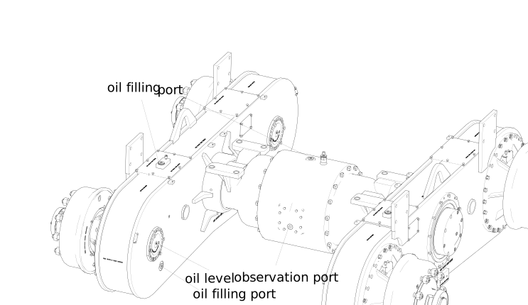 |
Figure1axle |
During field maintenance, the control of the amount of refueling shall be measured against the oil level hole, and a small amount of oil shall be allowed to spill. The oil level shall be off-line 8 mm below the oil level hole.
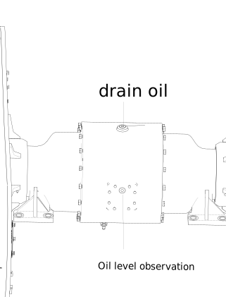 |
Figure2axle oil drain hole |
• | Add grease place and add grease amount |
greasing fitting in slewing bearing of the connection between balance box assembly and interrupt assembly
add grease equipment: manual pump
Grease is injected from the slewing bearing greasing fitting until the grease seeps out from the scraper seal. New grease must be added before and after the machine stops running for a long time.
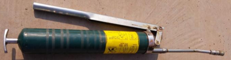 |
Figure3manual pump |
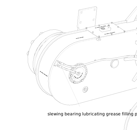 |
Figure4slewing bearing lubricating grease filling place |
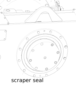 |
Figure5scraper seal |
• | Use and maintenance
|
• | Maintenance precautions
|
The specific adjustment methods are as follows:
Table1
name | active surface | driven surface |
Driven spiral bevel gear | 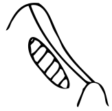 |  |
Active spiral bevel gear | 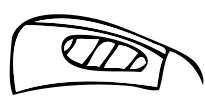 | 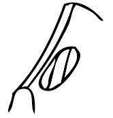 |
Table2
Contact position of driven gear surface | method of adjustment | Gear moving direction | |
 driving forward |  reversing | ||
 |  | Move the driven gear closer to the driving gear. If the clearance is too small, move the driving wheel outward |  |
 |  | Remove the driven gear from the driving gear. If the gap is too large, move the driving wheel inward |  |
 |  | Moving the driving gear closer to the driven gear, if the clearance is too small, move the driving gear outward |  |
 |  | Moving the driving gear away from the driven gear, if the clearance is too small, move the driving wheel inward |  |
• | Planetary gear reducer assembly adopts the form of "lock nut + tightening bolt + galvanized steel wire" to prevent loosening. |
After installing the double-row sprocket shaft assembly and gear ring assembly, tighten the nut until the planetary reducer housing cannot rotate, and then reverse the nut. During the reverse process, rotate the planetary reducer housing 3~5 times in the positive and negative direction by hand. Then install the fastening bolt and tighten it with 60~70 N. M torque. The two fastening bolts shall be alternately and evenly tightened and tightened with steel wire.Note that fastening bolts and steel wire shall not be higher than the end face of the double-row sprocket shaft.
• | When replacing the rolling needles in the planetary gear wheel of the planetary reducer, all the rolling needles shall be selected and matched in groups, so that the diameter difference within the same group is no more than 0.005 mm; Needle rolling cylindricity 0.003mm; The radial clearance between the needle roller, the gear inner hole and the planetary wheel shaft is 0.015 ~ 0.030 mm. |
• | Planetary reducer shall be ensured that the clearance between the adjusted strut and the limit block is 1 ~ 2mm while assembly after maintenance or replacement of half shaft. |
• | The rated working pressure of the brake is 8Mpa and the maximum working pressure is 10Mpa. The brake uses mineral oil. |
• | The brake assembly adopts the automatic gap adjusting brake sub-pump, when the brake friction disc has certain wear, it can automatically adjust the gap between the brake friction disc and the brake drum. When the brake friction disc is worn with the remaining 9.5mm, the friction disc must be replaced in pairs. |
Check the wear of the friction disc for the first time when the brake works with the main engine for 1000 hours. After that, the periodic inspection cycle is every 200 hours to check the friction wear.
• | The chain is a vulnerable part. In order to ensure the normal use of the grader bridge, when the sag of the loose side of the chain is greater than 18 mm, please replace it with a new chain. Check the tension of the chain for the first time when the chain works with the host for 100 hours. Subsequent periodic inspection cycle is every 500 working hours to check the tension of chain. |
• | In the maintenance work, apply solvent to clean the original parts coated with sealant. After drying, apply letai 598 sealant with a thickness of about 1 mm. Bolts should also be washed, dried in the thread end smear letai 263 anaerobic glue, tighten as required tightening torque. All seals, once removed, must be replaced, not reused. |
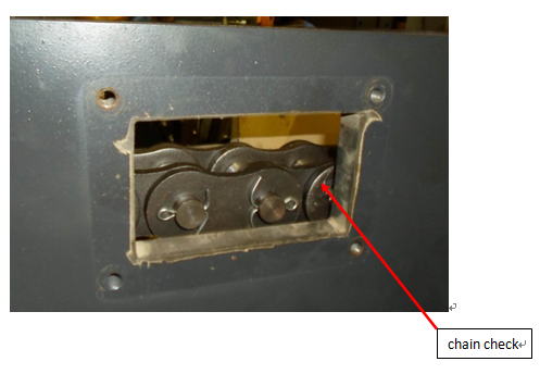 |
Figure6chain check |
Responsible for life:
1. | The information currently contained in this manual is valid and has been proofread. Changes due to product changes will not be subject to prior notice. XCMG Construction Machinery Co., Ltd. Reserves the right to modify or invalidate this product at any time. |
2. | During the quality assurance period, if any quality problems happen to the products, the user should contact us in time, we will appoint professional personnel to carry out maintenance. XCMG Construction Machinery Co., Ltd. Shall not be liable for all damages caused by unauthorized repair by the user. |
3. | The user shall strictly follow the instructions for operation and use. XCMG Construction Machinery Co., ltd. shall not be liable for the damage caused by the user's illegal operation. |


