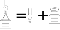
Rated lifting capacity is the permissible maximum net lifting load that the crane is designed to lift. The rated lifting capacity Q of mobile cranes includes the mass of the load, hook block and slings.
Figure 1Lifting load
2.
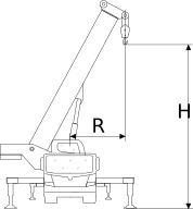
Lifting height (H) and working radius (R)
Figure 2Lifting height and working radius
Symbol
Name
Description
R
Working radius
The horizontal distance from the slewing center of the crane to the vertical center of the lifted load.
H
Lifting height
Lifting height is the vertical distance from the surface upon which the crane is supported to the bottom surface of the hook. The maximum lifting height represents the peak value that can be reached in terms of lifting height.
3.
Load moment (M)
Load moment is the product of the working radius R of the crane and the load G under the radius, i.e. M=R×G. Where lifting load (G)=lifting load (Q)× acceleration of gravity(g)
4.
Boom length (L) and boom angle (α)
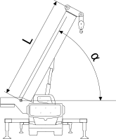
Figure 3Boom length and boom angle
Symbol
Name
Description
L
Boom length
Boom length is the distance from the rear pivot of the boom to the center line of the pulley on the boom head.
α
Boom angle
The angle formed between the center line of the boom and the horizontal plane.
5.
Jib length (L) and jib offset angle (γ)
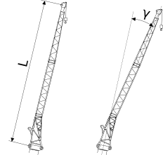
Figure 4Jib length and jib offset angle
Symbol
Name
Description
L
Jib length
Jib length is the distance from the rear pivot of the jib connecting bracket to the center line of the pulley on the jib head.
γ
Jib offset angle
Jib offset angle is the angle of the center line of the jib against the center line of the boom.
6.
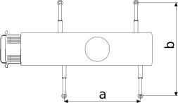
Outrigger span
The distance between the centers of the two outrigger floats.
Figure 5 Outrigger span
Symbol
Name
Description
a
Longitudinal span
The distance between outrigger vertical axes measured by the lines parallel to the longitudinal moving direction of the crane.
b
Transverse span
The distance between outrigger vertical axes measured by the lines vertical to the longitudinal moving direction of the crane.
7.
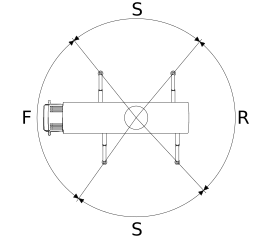
Working areas
G00660453
Figure 6Working areas
Symbol
Name
Description
F
Front working area
Front working area is an area over the front of the crane in which the boom may work. The boom capacity in this area is specified in Rated Load Charts. When the load to be lifted is very heavy, do not use the boom over the front working area, because in this case the stability of the entire crane is not good.
S
Side working area
Side working area is an area over the side of the crane in which the boom may work.
R
Rear working area
Rear working area is an area over the rear of the crane in which the boom may work. The boom capacity in this area is specified in Rated Load Charts.
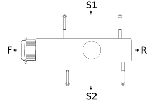
8.
Direction
The direction of the crane is ascertained based on the viewpoint of the driver in the cab.